Radiation maps for Eastern Japan

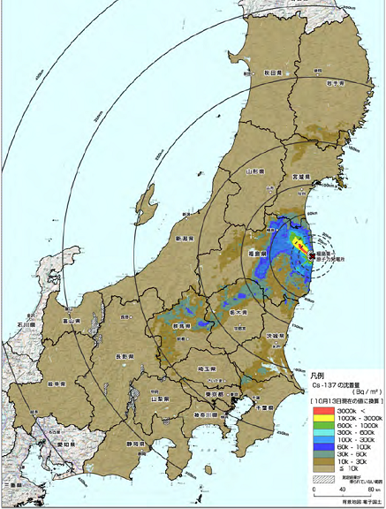
The Japanese government has released updated radiation maps for Eastern Japan from its helicopter survey. The maps now cover prefectures as far west as Gifu and as far north as Iwate and Akita. Previously there was map data only for Tokohoku (excluding Aomori) and the Kanto area. The PDF can be downloaded here.

The previous set of maps documented caesium contamination and background radiation levels in Fukushima, Tochigi, Miyagi, Ibaraki, Chiba, Saitama, Tokyo and Kanagawa. The latest set adds maps for Iwate, Shizuoka, Nagano, Yamanashi, Gifu and Toyama. Akita, Yamagata and Niigata have also been surveyed and are shown on the overview map.

The most heavily contaminated areas are in the eastern half of Fukushima prefecture, within about 80 km of the wrecked nuclear power stations. The southern part of Miyagi to the north and the northern part of Ibaraki to the south also took a hit.

A major radioactive plume moved south-west from Fukushima, polluting the northern half of Tochigi and the northern and western part of Gunma. A separate plume reached the southern part of Ibaraki, the north-west of Chiba and the eastern part of Tokyo.

There is also some caesium in the mountainous far west of Tokyo and Saitama that extended from Tochigi, but most of Saitama, Tokyo and Kanagawa seem relatively OK, as are Shizuoka, Yamanashi, Nagano, Gifu, Tokyama, Niigata, Yamagata and Akita. There is some fallout in a strip from southern Iwate to northern Miyagi, while central Miyagi and the rest of Iwate look clean. There is no published data for Aomori and Hokkaido yet, but based on the distance and the absence of significant pollution in Akita and adjacent parts of Iwate they will probably be fine.

The maps only give the overall picture, as there may be local hotspots in areas that are relatively clean overall, based on rainfall and wind patterns as well as soil and vegetation that can retain more or less fallout.

Update 2011-12-06:
The ministry has also published radiation maps for Aichi, Aomori, Ishikawa and Fukui prefecture.

How (not) to decontaminate Japan

An article in Japan Times (2011-11-09, “Scrub homes, denude trees to wash cesium fears away”) provided advice on how to decontaminate areas affected by nuclear fallout, such as in Fukushima, Tochigi and northern Chiba prefecture. Most of the advice is sound, but some is downright alarming:

As for trees, it’s best to remove all their leaves because of the likelyhood they contain large amounts of cesium, Higaki [of University of Tokyo] said.
(…)
What should you do with the soil and leaves?
(…)
Leaves and weeds can be disposed of as burnable garbage, a Fukushima official said.

So let me get this right: you should collect all those leaves because they contain so much radioactive cesium (cesium 134 has a half life of 2 years and cesium 137 of 29 years). And then, when you have all that cesium in plastic garbage bags, you have it sent to the local garbage incinerator, so the carefully collected cesium gets spread over the whole neighbourhood again via the incinerator smokestack. That makes no sense at all.

My Terra-P dosimeter (MKS-05) by Ecotest

Yesterday my geiger counter arrived here in Japan. It is a Terra-P dosimeter made by Ecotest, a company based in L’viv/Ukraine, about 300 km west of Chernobyl.

I bought the device on eBay from a supplier in Australia for US$399 including shipping. It arrived within 9 days and seems to work well. Although the buttons on my Terra-P are labelled in Cyrillic (either Russian or Ukrainian) and so is the manual, English manuals for it are easy to find online, so that’s not really a problem.

The Terra-P is a consumer grade dosimeter, so it’s not quite as versatile or as precise as professional devices costing $1000 or more, but it covers the basics very well. Its power source are two AAA-batteries, accessible via a lid at the back of the unit, which are easy to replace. It measures gamma rays and is suitable for checking for caesium contamination.

The user interface consists of an LCD, two buttons and speaker. One push of the right hand button (“режим” = mode) switches the dosimeter on and puts it into the measuring mode. The display switches to a microsievert per hour (µSv/h) readout. For the first 70 seconds the resulting number blinks, as it averages the dose over that period and the number gradually becomes more meaningful. After the initial sampling period, the number displayed will always be the average of the last 70 seconds, so you can move it from location to location and will get a decent result provided you wait for about a minute.

After several minutes the device enters power save mode, in which it continues counting radioactive decays, but the LCD is off and less power is used. To turn it off completely when it’s active, push the mode button once more and then push and hold it for four seconds, until the LCD blanks.

The Terra-P also has a user-settable alarm threshold (default: 0.30 µSv/h) and a clock mode. The built-in speaker usually makes one click for every gamma photon detected and sounds an alarm if the radiation exceeds the alarm threshold.

Checking my home after unpacking the device, I found the radiation level was a little higher than the 0.055 µSv/h reported for Tokyo by the local government, but still somewhat lower than the 0.10 µSv/h in my home town in Germany. On the other hand, I was relieved to see the wooden deck outside our living room was no more radioactive than inside the house. As expected, the gutters at the edge of the road, where rain water drains into the sewers, was more radioactive, with about 0.20 µSv/h, which is still far from alarming.

See also:

Radiation map of Japan

The Japanese government has published online map data about radiation levels in Eastern Japan. You can zoom in and out, scroll around and select data from:

  • Background radiation in microsievert per hour
  • Contamination by caesium 134 and 137 combined (Cs-134+Cs-137) in becquerel per square metre
  • Contamination by caesium 134 (Cs-134) in becquerel per square metre
  • Contamination by caesium 137 (Cs-137) in becquerel per square metre

The data was collected via helicopter flights carrying instruments that detect gamma radiation of different energy spectrums, allowing a breakdown by isotopes causing it.

There are the following data sets:

  • April 29
  • May 26
  • July 2
  • Miyagi prefecture, July 2
  • Tochigi prefecture, July 16
  • Ibaraki prefecture, August 2
  • Chiba and Saitama prefecture, September 12
  • Tokyo and Kanagawa prefecture, September 18

Click on this link:

either the online maps or download PDF files of the maps and click on “同意する” (“I do agree”, the left button) to get access.

The government is planning to extend the radiation survey to the whole of Japan, not just within about 250 km of the wrecked reactors as is currently the case.

See also:

Solar energy, USA vs. Germany

Recently I came across an article that quoted a Forbes commentary (“Sue OPEC? Congress Should Sue Itself”, 2008-07-09) comparing solar energy development in the USA (or lack thereof) with the situation Germany, where 2010 was a veritable boom year for photo-voltaic panels.

Two maps and one quote underneath caught my attention:

Check out the map above. With the exception of Seattle, the entire continental U.S. is much sunnier than Germany. Yet Germany has 17 times the installed solar base per capita.

According to the map, Germany received amounts of sunlight comparable to the region around notoriously cloudy Seattle and arctic Alaska, while most of the states along the Canadian border got 50% more sun than the Southern half of Germany.

This did not seem plausible to me. While it’s true that most of Germany lies further North than the 49th parallel that marks most of the US-Canadian border and should therefore receive less sun than most of the US, most of Germany’s climate is far sunnier than Seattle, which lies about as far North as Mannheim or Nuremberg (Nürnberg) in Southern Germany. Based on latitudes and annual rainfall, solar insolation (the amount of solar energy radiated onto a given area) should be largely comparable between at least southern Germany and the northern US outside the Pacific Northwest. I’ll give you some data to verify this theory.

Here is a map of insolation for the entire US, showing kWh per square metre per day at latitude tilt (multiply by 365 for annual figures like in the Forbes map):

As you can see, most of the US gets between 4 and 5.5 kWh/day (yellow-grey to dark yellow), or 1450-2000 kWh per year.

And here is a map of insolation in Germany, showing horizontal irradiation in kWh per square metre per year:

Note that the colour scale is not the same. The southern part of Germany gets 1200 kWh and more per year, the northern part less than that.

But that’s not the whole picture. If you you paid attention, you noticed the “at latitude tilt” (US) versus “horizontal irradiation” (Germany). It makes a big difference, because without taking it into account, the comparison of the raw numbers become an apples to oranges comparison: The numbers in both maps don’t actually measure the same thing!

The further you move north, the lower the sun stands at midday to the South. Consequently, when you install solar panels anywhere but in a tropical country, you don’t install them horizontally but make sure to tilt them at the right angle to catch the most sun per square metre of expensive panel, based on the average position of the sun at noon throughout the year, which depends on your distance from the equator. It will be more tilted at a more northern location than somewhere further south.

The US solar data is measured per square metre of panel. The German data however is per square metre of shadow the panels cast on the ground, which is not the same. The two ways of measuring insolation only match at the equator.

Let’s look at an example: In Chicago, at around 42 degrees North, a solar panel tilted 42 degrees towards south is exposed to 37% more sun than a flat piece of lawn of the same size (1/cos(42 degrees) = 1.37). So a one square metre panel’s 1500 kWh/year in total solar irradiation in Chicago is basically the same as 1100 kWh of horizontal exposure, which is the same or less than you catch just about anywhere in Germany. Far from being comparable only to rain-swept Seattle, Germany’s annual exposure to the sun is actually not too different from the US east of the Mississippi, except for the Southern sunbelt from Texas to Florida, which does get more sun.

So what do we learn from this?

1) As our physics teacher always used to tell us: Watch your units! Numbers don’t tell you anything unless they go with the proper unit.

2) The German solar subsidy program is no crazy boondoggle at taxpayer’s expenses. Solar energy does make sense in Germany, as it does in most other countries in temperate climates.

Of course it makes even more sense in dry climates like Spain, Turkey, North Africa and the arid US Southwest, where it’s ideal. On the other hand, Seattle or Iceland may not be the greatest places for it.

Ideally, solar energy investment should start where it brings the highest returns, accompanied by sufficient investment into a power grid that can carry power wherever it’s needed.

In 2010, Germany produced about 1.9% of its electricity usage from solar panels, almost double what it was the year before. By 2020 this is expected to more than triple again, to 40 GWh or 6%. As mass production brings costs down while oil prices keep going up, German solar electricity is expected to become cost-competitive with conventional power by about 2015, which will be great for cutting dependence on dwindling oil reserves.

Also, let’s not forget that solar energy is not the only renewable game in town: Wind for electric power is already much more competitive on a cost per kWh basis than photovoltaics and deserves more attention. Many regions that have relatively poor solar prospects have excellent wind opportunities, for example Scotland. A mix of solar and wind often works better than just one or the other.

Germany has great potential for wind power, both land based and off-shore, and so do the US. What is holding wind power back particularly in the US (but to some extent also in Germany), is an under-sized grid that can not move enough power over the necessary distances from areas with plentiful wind to where the power is needed. Investment in a 21st century power grid will be essential for a low-carbon future.

Tepco’s unfiltered vent path

On August 13, 2011 I wrote about TEPCO not adding filters to their reactors even decades after Sweden did. Since the, on August 16, 2011, Tepco defended not having any kind of filters in the so-called “hardended vent” path between the containment and the exhaust stack:

Corrections and Clarification of a news report program, “ETV Special” by NHK, broadcasted on August 14

August 16, 2011
Tokyo Electric Power Company
NHK TV program regarding Fukushima Daiichi Nuclear Power Station reported contents that are incorrect and could cause misunderstandings. We hereby provide facts below.
(…)
3. Claim on the PCV ventilation has no filtration
In the program, it was mentioned several times that there were no filters in the primary containment vessel ventilation line. However, boiling water reactors that we operate use “wetwell vent”, which has scrubbing effect to mitigate emission of radioactive materials at the comparative level to the filters. That is to say, in principle, our venting procedure uses the water in the suppression chamber as filteration and we have prepared and added the necessary equipment and procedures for accident management measures.

Tepco’s reactors have a “Standby Gas Treatment System” for filtering gases released into the atmosphere. This system is claimed to be at least 97% effective in unit 1 and at lest 99.9% effective in units 2 and 3. However, it can’t be used for venting high pressure gas from the drywell or wetwell (the containment) in emergencies. In the above press release Tepco defends its decision by claiming that the water pool in the suppression chamber (wetwell) is as effective as some other kind of filter system that it could have had installed when adding the hardended vent path in 1999-2001.

This claim is disingenuous. The FILTRA system installed at the Swedish Barsebäck nuclear power station was in addition to any filtration provided by the wetwell pool, not in place of it. Barsebäck had boiling water reactors like in Fukushima (the plant has since been decommissioned).

Furthermore, it’s not clear how effective the filter effect of the wetwell on its own really is. A US report from 1988 entitled “Filtered venting considerations in the United States” writes:

Within the United States, the only commercial reactors approved to vent during severe accidents are boiling water reactors having water suppression pools. The pool serves to scrub and retain radionuclides. The degree of effectiveness has generated some debate within the technical comnunity. The decontaminatlon factor (DF) associated with suppression pool scrubbing can range anywhere from one (no scrubbing) to well over 1000 (99.9 % effective). This wide band is a function of the accident scenario and composition of the fission products, the pathway to the pool (through spargers, downcomers, etc.), and the conditions in the pool itself. Conservative DF values of five for scrubbing in MARK I suppression pools, and 10 for MARK II and MARK III suppression pools have recently been proposed for licensing review purposes. These factors, of course, exclude considerations of noble gases, which would not be retained in the pool.

The decontamination factor of 5 for the Mark I containment (as used in units 1 through 5 of Fukushima Daiichi) means that 80% of the radioactive substances (excluding noble gases) is retained, while 20% is released. The FILTRA system installed at 10 Swedish nuclear power plants and one in Switzerland is designed to ensure that in a severe accident 99.9% of core inventory is retained in the containment or the filters. The difference between releasing up to 20% versus 0.1% is huge, it means up to 200 times more radioactivity is released in the system defended by Tepco versus the enhanced system used in Europe and commercially available worldwide.

Fukushima: Keep out indefinitely

The government of Japanese prime minister Kan is finally telling evacuees from within the 20 km exclusion zone around the wrecked Fukushima-I nuclear power plant that they won’t be able to return any time soon.

For months the official line had been that residents could not return until the reactors had achieved “cold shutdown”, which normally means that the chain reaction had stopped and the decay heat in the core had subsided enough for the coolant to be below 100 degrees C (below boiling point). This line ignores the fact that three of the reactors no longer have a cooling system in the usual sense and more importantly, that the area around the power station was severely contaminated by radioactive fallout from the broken reactors.

That reality has finally been accepted, explains the New York Times:

The government was apparently forced to alter its plans after the survey by the Ministry of Science and Education, released over the weekend, which showed even higher than expected radiation levels within the 12-mile evacuation zone around the plant. The most heavily contaminated spot was in the town of Okuma about two miles southwest of the plant, where someone living for a year would be exposed to 508.1 millisieverts of radiation — far above the level of 20 millisieverts per year that the government considers safe.

The survey found radiation above the safe level at three dozen spots up to 12 miles from the plant. That has called into question how many residents will actually be able to return to their homes even after the plant is stabilized.

Many of the evacuees had been led to believe that most of them might be able to return to their homes some time after the turn of the year, based on Tepco’s promises of establishing some sort of a cooling system and generally stabilizing the situation at the plant. Probably over 100,000 people will have to rebuild their lives from scratch elsewhere now, with no prospect of returning for decades, just like in the exclusion zone in Ukraine and Belarus near the Chernobyl plant, that has been off-limits for over a quarter of a century already. Besides a semicircle of 20 km radius around Fukushima-I there is also a strip of land to the North West, towards Fukushima City, that includes the village of Iitate mura, which is just as badly contaminated as the vicinity of the reactor itself.

People from the area should have been told much sooner, but presumably the prospect of having to pay compensation played a part in holding off giving people the facts. If somebody other than Kan was prime minister, they may well have waited for another 6 months. Kan will probably step down shortly and frankly I don’t hold much hope for how his successor, whoever he may be, will deal with the situation.

Kan famously took on ministerial bureaucracies and vested interests as health minister before and he tried his best in this situation. Many others would try to avoid confrontation with the nuclear industry, following the path of least resistance instead. Kan’s support ratings are extremely low now, but perhaps his efforts, however imperfect they were, may not be fully appreciated until we have his successors to compare with…

APC Smart-UPS 750 with Ubuntu 11.4


I finally got myself an uninterruptible power supply (UPS). The infamous August heat in Tokyo has been pushing power use including air conditioning close to the limit of what Tepco can supply: All 10 reactors in Fukushima Daiichi and Daini are either destroyed or shut down. In total about 2/3 of the nuclear power capacity in Japan is currently offline. That gave me one more reason to shop for a UPS. The other was that I have a Linux server and Linux file systems tend to use a lot of write buffering, which can make a mess of a hard disk partition if power is lost before the data is fully written to disk.

A friend recommended APC as a brand. Researching which of their ranges was suitable for my server, it appeared that some advanced PC power supplies with Power Factor Correction (PFC) have problems with the consumer level APC models, which output a square wave when in battery power mode. The more business-oriented models output something closer to a sine wave, the shape of power supplied by your utility company. Because of that I went for the APC Smart-UPS range. The server draws less than 50W, so there wasn’t really much point going for the beefiest models. That’s how I picked the APC Smart-UPS 750 with 500W of output power. My exact model is the SUA750JB, the 100 V, 50/60 Hz model for Japan. If you live in North America, Europe, Australia or New Zealand you’ll use either the 120V or 230V models. There’s also a 1000W (1500 VA) model, the APC Smart-UPS 1500, which features a larger capacity battery and larger power output.

The UPS arrived within two days. There’s a safety plug at the back of the unit which when open disconnects the battery for transport, which you’ll have to connect to make it work. The internal lead-acid batteries appeared to come fully charged. They are fully sealed units that are supposed to be leak-proof.

My unit came with a manual in Japanese and English but no software of any kind. It came with a serial cable, which I don’t have any use for, as virtually all modern PCs no longer have legacy serial and parallel ports. What I needed was a USB cable with one type A and one type B connector and that was not included. I am not sure why APC bundles the serial cable and not the USB cable. For an item in this price range, the USB cable should not be extra. However, I had a couple of suitable cables lying around from USB hard disks and flat screen monitors with built-in USB hubs, so it wasn’t a problem. You may want to check if the unit you’re buying comes bundled with the USB cable or if you may need to get one separately.

Once you connect the UPS to the PC using a USB cable, you should be able to verify that Linux has detected the device. Run:

me@ubuntu-pc:~$ lsusb
Bus 003 Device 003: ID 051d:0002 American Power Conversion Uninterruptible Power Supply

The software I’m using for linux is the apcupsd daemon, whose source code is available on SourceForge. I compiled it this way:

./configure --enable-usb
make
sudo make install

To be able to run it you need to set some config files. In /etc/default/apcupsd set

ISCONFIGURED=yes

In /etc/apcupsd/apcupsd.conf:

UPSCABLE usb (default: smart)
UPSTYPE usb (default: apcsmart)
DEVICE (default: /dev/ttyS0)

Stop and start the daemon and you’re in business:

/etc/init.d/apcupsd stop
/etc/init.d/apcupsd start

While the daemon is stopped you can also run apctest to run various tests on the unit.

Test that the UPS works, by pulling the power cable from the wall socket. The UPS should raise an audible alarm and its LEDs should switch from the sine wave symbol to the sine wave with battery poles symbol. Also be aware that UPS batteries do not last forever, especially if they’re used in a hot environment. You may get anywhere between 2 to 4 years of use out of them. Replacement batteries from third parties are usually available for much less than original parts from the UPS manufacturer.

Tepco and the dirty secret of the radioactive stack

On July 31, 2011 Tepco detected a radioactive hotspot at the base of an exhaust stack serving units 1 and 2 of Fukushima Daiichi. The following day, a measurement showed the activity to be more than 10 Sv/h (10,000 mSv/h), the highest measured in any accessible part of the wrecked nuclear power station so far (see “The worst hot spot in Fukushima“).

The high activity is assumed to date from attempts at venting the containment of unit 1 on March 12, after it had suffered core damage the previous evening. The venting, necessary to prevent the containment from bursting from excessive pressure, used a so called “hardened vent path” installed by Tepco between 1999 and 2001, following similar upgrades in the US after the Three Mile Island accident.

The reactors have filter system known as the “Standby Gas Treatment System” (SGTS), located on the second floor of the reactor building right next to the turbine hall, but the SGTS doesn’t work without electricity, i.e. the condition that triggered core damage in Fukushima Daiichi. Also, gas from the containment is released at high pressure, which would overwhelm the SGTS.

Therefore the gas is released untreated. Via a strong steel pipe it flows directly into the base of an over 100 m tall exhaust stack. High altitude winds carry it away from the plant. The only filtering that has taken place before than is by water in the pressure suppression pool at the bottom of the containment, through which any gas releases from the reactor pressure vessel are forced to bubble. As the high radioactivity level around the stack demonstrates some 5 months later, there is still plenty of activity left in the gas after that “wet scrubbing”.

It didn’t have to be that way. First of all, if Tepco had built the reactors at a higher location or surrounded them with a sea wall to protect them from a 14 meter high tsunami, there probably would not have been a total station blackout and hence a failure of the residual heat removal system (RHR). The cores wouldn’t have melted. It has long been known that the relatively small Mark 1 containment of these Boiler Water Reactors (BWRs) have problems dealing with vast volumes of hydrogen gas produced when core damage occurs. There was no way to make the containment bigger, short of decommissioning the old reactors and building new ones, which would have cost a lot of money. But that wasn’t the only option.

In 1981, Sweden came up with the FILTRA system for their Barsebäck nuclear power station, which consisted of two BWRs similar in size and functionality to the units in Fukushima. Construction of Barsebäck had started in 1969, only two years after the first unit in Fukushima. It was located about 500 km south of the Swedish capital of Stockholm, but only 20 km from the Danish capital of Copenhagen. The Copenhagen metropolitan region is home to about 1.9 million people in Denmark and South Sweden is also one of the most densely populated parts of the country.

The FILTRA system consists of concrete pipes or rock tunnels filled with gravel, through which the released gas must flow. It gives off heat to some 10,000 m3 of rock, which condenses steam and radioactive fission products, which collect at the bottom of the gravel chambers. After the gas has cooled it is sent through sand or water for further filtration. Only then is it released in the stack. The system is simple and robust enough to cope with high pressure and temperatures. Since it doesn’t use any high technology it was relatively cheap to build.

There was plenty of space available at Fukushima. The Swedish system was no secret. Here is the 30 year old report that discussed its details. Why did Tepco not build a filter system like that, to be shared among its 6 units at Fukushima Daichi? By building the hardened vent path, it already admitted to the possibility of a core meltdown, so why not make sure the venting could be cleaned up? Perhaps Tepco didn’t want to spend more money on safety than it absolutely had to. Perhaps it was also because the Swedish reactors were designed by Asea-Atom AB, whereas the Fukushima design was by GE. Whatever the reason, the technology to protect the people of Japan in a nuclear accident has been available for three decades and Tepco chose not to use it.

The worst hot spot in Fukushima

A week ago, Tepco detected radiation exceeding 10,000 mSv/h (i.e. 10 Sv/h) at an outdoor location near unit 1. This is the highest dose so far recorded outside a reactor core at the site. The previous record was 4,000 mSv/h in unit 2. To put this in perspective, about 7 Sv is already a fatal dose. Therefore 40 minutes at that location would mean certain death from radiation sickness. The local hourly dose of 10 Sv is 100 times as much as the 100 mSv a nuclear worker may normally be exposed to over a total of five years. It is 40 as much as the 250 mSv the government has permitted workers to be exposed to during the Fukushima disaster efforts.

While it’s alarming to hear about record radiation levels being found months after three of the reactor buildings exploded, most likely this radiation is not something new but has been there since the early days of the disaster. It was detected at two locations, an outdoor stack serving units 1 and 2 for venting purposes, and an indoor filter room on the second floor of the turbine hall of unit 1. Both locations are connected using a high pressure steel pipe used for emergency venting. Tepco recently started some construction work near the stack, erecting a steel and plastic cover around unit 1 and perhaps that increased human activity around there led to the discovery.

When Fukushima-I was hit by a station blackout (total electric power failure) after being flooded by a 14 meter high tsunami on March 11, 4 of its reactors and their spent fuel pools were left without cooling. As a result, the cores of units 1, 2 and 3 overheated and their fuel rods melted. During the overheating, steam was vented from the reactor pressure vessel into the suppression chamber of the containment vessel, until the relatively low design limit of the containment was exceeded. In order to not risk an explosion, the operators at that point decided to release radioactive gasses from the containment through the emergency venting system, which is connected to the exhaust stacks.

If during normal operation of the power plant any gases have to be released, they are treated via the Standby Gas Treatment System (SGTS), which comprises HEPA filters followed by active charcoal filters. The unit 1 SGTS is claimed to capture better than 97% of iodine, while units 2 and 3 have a claimed retention rate of better than 99.9%. Treated gas is sent by electrically operated blowers to the exhaust stack, where winds would usually disperse it over the sea. If you look at aerial pictures of the station (see last picture), you see large pipes running from the units to the stacks. Unit 1 and 2 share one stack, units 3 and 4 another (unit 4 was shut down for repairs at the time). These are low pressure pipes, designed for relatively slow releases. Each unit has two systems capable of handling 0.5 m3/s (unit 1) or 0.75 m3/s (units 2/3) each. Because the SGTS relies on electric blowers it is not usable during a total station blackout.

Next to the fat pipes are much thinner high pressure pipes, which are part of the “hardened venting system” installed by Tepco between 1999 and 2001. They were added specifically for major disasters, when the pressure inside the containment reaches dangerous levels, requiring an urgent release of pressure. The hardened venting system skips the charcoal filters. Its only filtering mechanism is the water pool in the suppression chamber, through which steam vented from the reactor core first bubbles. Its scrubbing effect is much more crude than the normal gas filters. The efficient filtering system can not be used during high pressure containment venting because it would offer too much resistance and could not stand the heat or pressure of an emergency release. Yet I still remember when a government spokesman announced that Tepco was going to vent the unit 1 containment into the atmosphere on March 12, we were told that the venting would be filtered, which wasn’t really true.

radiation measurement at bottom of unit 1/2 vent stack

A June 2011 report by the Japanese government to the IAEA explains on page IV-13:

TEPCO built new vent pipes extending from the S/C and D/W [suppression chamber and dry well, the two parts of the containment vessel, JW] to the stacks from 1999 to 2001 as PCV [primary containment vessel, JW] vent facilities during severe accidents as shown in Figs. IV-2-13 and IV-2-14. These facilities were installed to bypass the standby gas treatment system (hereinafter referred to as SGTS) so that they can vent the PCV when the pressure is high.
The facilities are also provided with a rupture disk in order to prevent malfunction.

As the pressure dropped in the hot, compressed gases from the containment and they came into contact with the cooler pipes leading to the stack, the gas cooled off and there was condensation inside the pipes. Some radioactive fission products from the melted fuel rods must have been deposited on the pipe walls. Radiation from these deposits is penetrating the pipe walls, causing high levels at the base of the exhaust stack and inside the filter room through which the venting pipe runs.